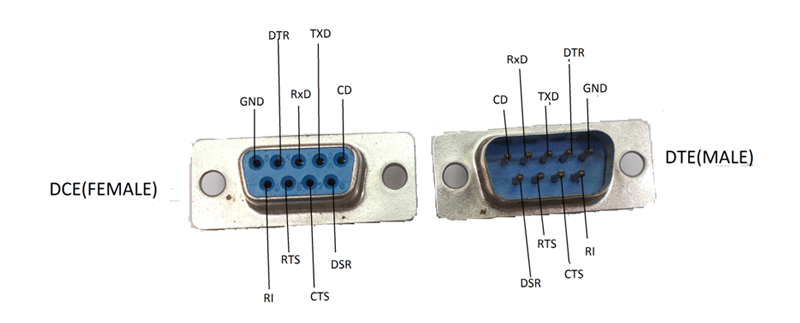
9 Pin Serial Port Wiring Diagram
Get 9 Pin Serial Port Wiring Diagram Gif. This is in contrast to a parallel port. Add serial communication functionality to your windows application.
The hub can detect the attachment or detachment of devices in each port of the hub.
How do i wire up my arduino (uno) to the 9 pin serial connector so that i can read the ack (and in future write back) and display the ack signal in you can use any digital io on uno then, and control it in software. The first serial port is configured as a serial console, but you can choose to unconfigure it to free it for other applications. Connect the serial port (rxd, txd) of the usb serial or mcu to the module, and connect the pwrc pin of the module to the power supply (vcc, gnd) of the module when sending. The usb cable has typically four wires to connect the a type connector.

0 Response to "9 Pin Serial Port Wiring Diagram"
Post a Comment