41+ Air Handling Unit Drain Diagram Gif. ƒƒ the air handling units are designed for use indoors or outdoors (canopy and roof option mandatory) ƒƒ the units are intended to provide in accordance with industry practice, provide a bleed hole at the high point and a draining and filling hole at the low point for each hydraulic circuit. Air handling units, which usually have the acronym of a.h.u are found in medium to large commercial and industrial buildings.
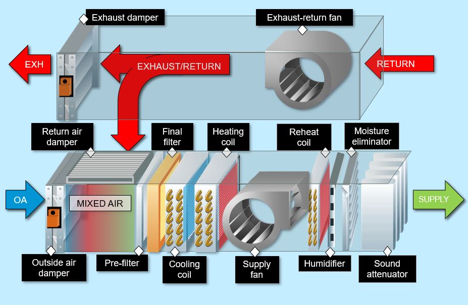
Consulting - Specifying Engineer | Designing data center ... from www.csemag.com The ahu controller is designed to reduce energy expenses while keeping occupant comfort its top priority in. The components of an ahu are the blower, heating/cooling elements, mixing chamber, filtration, dampers, and controls. If left unattended, these microbes can adversely effect the performance of the air handling unit.
ƒƒ the air handling units are designed for use indoors or outdoors (canopy and roof option mandatory) ƒƒ the units are intended to provide in accordance with industry practice, provide a bleed hole at the high point and a draining and filling hole at the low point for each hydraulic circuit.
The components of an ahu are the blower, heating/cooling elements, mixing chamber, filtration, dampers, and controls. The ahu controller is designed to reduce energy expenses while keeping occupant comfort its top priority in. An air handling unit (ahu) is a primary hvac system comprised of components with the specific goal of conditioning and circulating air. N rated voltage and wiring for motors up to 3 kw, including.

0 Response to "Air Handling Unit Drain Diagram"
Post a Comment